Modelling by numbers
An introduction to procedural geometry
(This is the third part of a four part tutorial. If you haven’t already, you should check out Modelling by numbers: Part One A)
Part Two A: The cylinder
Unity assets – Unity package file containing scripts and scenes for this tutorial (all 4 parts).
Source files – Just the source files, for those that don’t have Unity.
Welcome to part two. This is where we move on to our second basic shape: the cylinder.
A note about maths
Curvy things are a little more maths-heavy than the shapes we’ve covered so far. Some basic maths (particularly trigonometry) knowledge will be helpful here. Nothing fancy, and you can always just copy the code if you want. But if you can remember the basic trig ratios and know the difference between degrees and radians, then you’ll be better equipped to actually understand what’s going on.
The basic cylinder
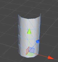
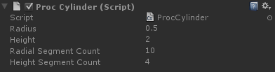
This is the second of our basic building blocks, and a very handy one, too.
Building a cylinder requires a similar approach to building the ground plane in part one of this tutorial. Except that instead of rows and columns we’re now dealing with rings and columns.
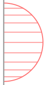
The first step, therefore, is learning how to make a ring. Going back to high school maths, the X and Y values of a unit vector will always be the cosine of the angle between the vector and X axis, and the sine of that angle, respectively. As the angle moves from 0 to 360 degrees, the points will form a circle.
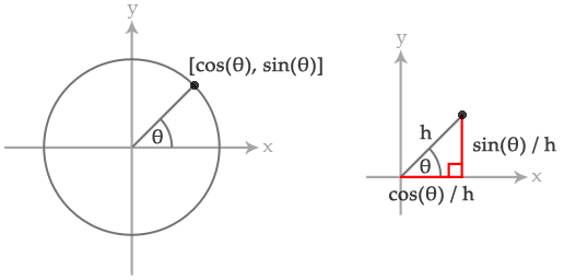
Alternatively, I’ll explain in code:
float radiansInACircle = Mathf.PI * 2;

for (int i = 0; i < segmentCount; i++)
{
	float angle = radiansInACircle * i / segmentCount;

	Vector2 position = new Vector2(Mathf.Cos(angle), Mathf.Sin(angle));
}
The result of this will be that all of those positions will form a circle (with a radius of one).
Something worth pointing out at this point: you’ll notice that this code gives the angle in radians. This is required for the Mathf trigonometric functions, unlike the entire rest of Unity, which expects angles to be in degrees. In our scripts, we’re going to follow the same pattern and work with degrees, converting when entering trigonometric code.
Right, let’s build a ring:
void BuildRing(MeshBuilder meshBuilder, int segmentCount, Vector3 centre, float radius,
	float v, bool buildTriangles)
{
	float angleInc = (Mathf.PI * 2.0f) / segmentCount;

	for (int i = 0; i <= segmentCount; i++)
	{
		float angle = angleInc * i;

		Vector3 unitPosition = Vector3.zero;
		unitPosition.x = Mathf.Cos(angle);
		unitPosition.z = Mathf.Sin(angle);

		meshBuilder.Vertices.Add(centre + unitPosition * radius);
		meshBuilder.Normals.Add(unitPosition);
		meshBuilder.UVs.Add(new Vector2((float)i / segmentCount, v));

		if (i > 0 && buildTriangles)
		{
			int baseIndex = meshBuilder.Vertices.Count - 1;

			int vertsPerRow = segmentCount + 1;

			int index0 = baseIndex;
			int index1 = baseIndex - 1;
			int index2 = baseIndex - vertsPerRow;
			int index3 = baseIndex - vertsPerRow - 1;

			meshBuilder.AddTriangle(index0, index2, index1);
			meshBuilder.AddTriangle(index2, index3, index1);
		}
	}
}
This is a modified version of the grid-building code from our ground mesh in part one. Instead of incrementing a position offset, we’re incrementing an angle. From that angle we can get a unit position (a position one unit away from the centre) in the XZ plane. Multiply by the radius and add the centre offset and we have the position of our vertex.
The normals of this mesh all face directly outward from the centre axis. Happily for us, this means that the normal and the unitPosition are the same.
If we call this function once for the bottom of the cylinder, and once for the top, we’ll have a basic cylinder:
BuildRing(meshBuilder, m_RadialSegmentCount, Vector3.zero, m_Radius, 0.0f, false);
BuildRing(meshBuilder, m_RadialSegmentCount, Vector3.up * m_Height, m_Radius, 1.0f, true);
This is perfectly adequate if we never want to deform the cylinder, although the lighting may have a little bit of trouble with the very long triangles. Let’s modify our code to divide the height into segments.
float heightInc = m_Height / m_HeightSegmentCount;

for (int i = 0; i <= m_HeightSegmentCount; i++)
{
 	Vector3 centrePos = Vector3.up * heightInc * i;
 	float v = (float)i / m_HeightSegmentCount;
 	BuildRing(meshBuilder, m_RadialSegmentCount, centrePos, m_Radius, v, i > 0);
}
Again, just like our ground mesh code, except we’re only incrementing the height, and we’re building rings rather than rows.
Hang on, that’s not a cylinder! What about the caps?
You may want to cap the ends of this mesh and make it a proper cylinder. This is likely to be necessary if your cylinder is going to stay as it is and not become something else. Usually, the cylinder will be the first stage of a more complicated mesh, and much of the time caps will not be required. In fact, you know what? I’ve never had to cap one before.
But, if you insist, let’s do this. A simple way would be create a vertex at the center of the cap, and build a triangle between that and each side.
void BuildCap(MeshBuilder meshBuilder, Vector3 centre, bool reverseDirection)
{
	Vector3 normal = reverseDirection ? Vector3.down : Vector3.up;

	//one vertex in the center:
	meshBuilder.Vertices.Add(centre);
	meshBuilder.Normals.Add(normal);
	meshBuilder.UVs.Add(new Vector2(0.5f, 0.5f));

	int centreVertexIndex = meshBuilder.Vertices.Count - 1;

	//vertices around the edge:
	float angleInc = (Mathf.PI * 2.0f) / m_RadialSegmentCount;

	for (int i = 0; i <= m_RadialSegmentCount; i++)
 	{
 		float angle = angleInc * i;

 		Vector3 unitPosition = Vector3.zero;
 		unitPosition.x = Mathf.Cos(angle);
 		unitPosition.z = Mathf.Sin(angle);

 		meshBuilder.Vertices.Add(centre + unitPosition * m_Radius);
 		meshBuilder.Normals.Add(normal);

 		Vector2 uv = new Vector2(unitPosition.x + 1.0f, unitPosition.z + 1.0f) * 0.5f;
 		meshBuilder.UVs.Add(uv);

 		//build a triangle:
 		if (i > 0)
		{
			int baseIndex = meshBuilder.Vertices.Count - 1;

			if (reverseDirection)
				meshBuilder.AddTriangle(centreVertexIndex, baseIndex - 1,
					baseIndex);
			else
				meshBuilder.AddTriangle(centreVertexIndex, baseIndex,
					baseIndex - 1);
		}
	}
}
This is a modification of the BuildRing() code. Instead of building a quad between the current vertex, the previous vertex, and the previous ring, we build a triangle between the current vertex, the previous vertex, and the centre vertex.
Our UVs use the unitPosition, halved and offset by 0.5, meaning that the cap will be mapped in a circle across the UV space, centred on [0.5, 0.5].
The reverseDirection argument does two things: reverse the normal, and switch the winding order of the triangles. The end result being that the cap faces in the opposite direction. Now we can use this to cap both the top and bottom of our cylinder:
BuildCap(meshBuilder, Vector3.zero, true);
BuildCap(meshBuilder, Vector3.up * m_Height, false);
Cylinder deformation – bending
Slightly more complicated is bending the cylinder. This requires a second, vertical circle to be calculated. Our cylinder, instead of pointing straight up, will follow the edge of this circle.
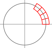
We need to calculate some things first:
float bendAngleRadians = m_BendAngle * Mathf.Deg2Rad;
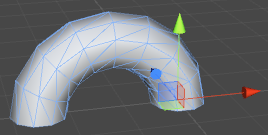
Our bend angle is how much we want the cylinder to bend. A bend of 90 degrees will give us a right angle bend, and 360 degrees will give us a doughnut shape. m_BendAngle is, following the convention we described before, defined in degrees. As we’re about to enter trigonometry land, we need it converted.
float bendRadius = m_Height / bendAngleRadians;
This is the radius of our second circle. This has to be such that an arc defined by our bend angle will equal the height of the cylinder. This way the cylinder stays the same length as it bends. As radians, by definition, are the arc length of a unit circle, we just need to divide the height by this length.
float angleInc = bendAngleRadians / m_HeightSegmentCount;
This is how much we want increment the angle each time the height loop runs. It works much the same way as angleInc inside the BuildRing() function. Because we’re dividing the angle by the segment count, rather than dividing 2PI, we’ll get the arc rather than a full circle.
Vector3 startOffset = new Vector3(bendRadius, 0.0f, 0.0f);
This is the position on our vertical circle where the angle is equal to zero. X is equal to the cosine of zero times the radius (ie. bendRadius * 1) and Y is the sine of zero times the radius (bendRadius * 0). This is where the base of our cylinder would go, if we let it. The problem is that we want the origin of our mesh at zero, not off to the side of the vertical circle, so all the rings need to be pulled over to the center. We will use startOffset to do this.
Now on to our height loop:
for (int i = 0; i <= m_HeightSegmentCount; i++)
{
	Vector3 centrePos = Vector3.zero;
	centrePos.x = Mathf.Cos(angleInc * i);
	centrePos.y = Mathf.Sin(angleInc * i);

	centrePos *= bendRadius;
	centrePos -= startOffset;

	float v = (float)i / m_HeightSegmentCount;

	BuildRing(meshBuilder, m_RadialSegmentCount, centrePos, m_Radius, v, i > 0);
}
Here we have the familiar circle code, applied in the XY plane. The position of the point on the circle becomes the center of that ring.
We subtract the start offset from the centre position to force the base of the cylinder (where the angle is zero) back onto the origin. If we wanted, we could just subtract bendRadius from the X position, rather than using a Vector3. However the Vector3 code leaves us ready for starting angles other than zero (which we will need later for other shapes).
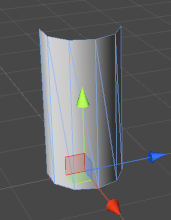
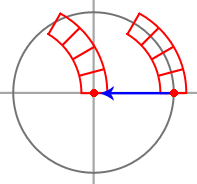
Let’s have a look:
Well, the cylinder as a whole is following the arc, but each ring is flat, as if the cylinder was still vertical. Also the lighting looks strange. This is because all the normals are still acting as though there was no bend.
What we need to do is rotate each ring:
for (int i = 0; i <= m_HeightSegmentCount; i++)
{
 	Vector3 centrePos = Vector3.zero;
 	centrePos.x = Mathf.Cos(angleInc * i);
 	centrePos.y = Mathf.Sin(angleInc * i);

 	float zAngleDegrees = angleInc * i * Mathf.Rad2Deg;
 	Quaternion rotation = Quaternion.Euler(0.0f, 0.0f, zAngleDegrees);

 	centrePos *= bendRadius;
 	centrePos -= startOffset;

 	float v = (float)i / m_HeightSegmentCount;

 	BuildRing(meshBuilder, m_RadialSegmentCount, centrePos, m_Radius, v, i > 0, rotation);
}
We calculate a rotation using the current angle around the Z axis. Note that we need to convert the angle back to degrees for this.
So, how does the BuildRing() function then use the rotation?
void BuildRing(MeshBuilder meshBuilder, int segmentCount, Vector3 centre, float radius,
	float v, bool buildTriangles, Quaternion rotation)
{
	float angleInc = (Mathf.PI * 2.0f) / segmentCount;

	for (int i = 0; i <= segmentCount; i++)
	{
		float angle = angleInc * i;

		Vector3 unitPosition = Vector3.zero;
		unitPosition.x = Mathf.Cos(angle);
		unitPosition.z = Mathf.Sin(angle);

		unitPosition = rotation * unitPosition;

		meshBuilder.Vertices.Add(centre + unitPosition * radius);
		meshBuilder.Normals.Add(unitPosition);
		meshBuilder.UVs.Add(new Vector2((float)i / segmentCount, v));

		if (i > 0 && buildTriangles)
		{
			int baseIndex = meshBuilder.Vertices.Count - 1;

			int vertsPerRow = segmentCount + 1;

			int index0 = baseIndex;
			int index1 = baseIndex - 1;
			int index2 = baseIndex - vertsPerRow;
			int index3 = baseIndex - vertsPerRow - 1;

			meshBuilder.AddTriangle(index0, index2, index1);
			meshBuilder.AddTriangle(index2, index3, index1);
		}
	}
}
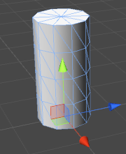
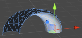
A very simple change. All we are doing is rotating the unit position. Both the vertex positions and the normals are now properly offset:
Important: Why, hello, Divide-by-Zero.
Something important to remember: This code breaks if the bend angle is zero. The vertical circle would have an infinite radius, as the cylinder can never bend around to meet itself. Because of this, our script needs to check the bend angle and just build a normal cylinder if it’s zero:
if (m_BendAngle == 0.0f)
{
	//Build a normal cylinder
}
else
{
	//Build a cylinder with a bend deformation
}
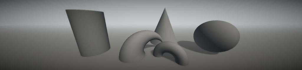
A common cylinder deformation, the sphere

Spheres can also be made by deforming cylinders. The method is not completely dissimilar to the way we made our bent cylinder. We use a second, vertical circle, but instead of using it to offset the centre of each ring, we use it to offset the radius.
int heightSegmentCount = m_RadialSegmentCount / 2;

float angleInc = Mathf.PI / heightSegmentCount;

for (int i = 0; i <= heightSegmentCount; i++)
{
	Vector3 centrePos = Vector3.zero;

	Vector3 centrePos.y = -Mathf.Cos(angleInc * i) * m_Radius;
	float radius = Mathf.Sin(angleInc * i) * m_Radius;

 	float v = (float)i / heightSegmentCount;

	BuildRing(meshBuilder, m_RadialSegmentCount, centrePos, radius, v, i > 0);
}
Here, we are applying the coordinates of our second circle to the height and radius of the ring. Essentially, the second circle defines a vertical cross-section.
A minor point: to keep the number of segments in the vertical plane the same as in the horizontal, we use half the number of height segments as radial segments. Our vertical curve defines a semi-circle rather than a full one.
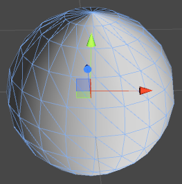
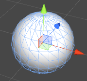
Looking at the result, we have a similar story to the cylinder bend. This time the shape is correct, but the normals are wrong. They are all pointing straight outward in the XZ plane, when we actually need a vertical tilt as they get toward the poles. We need to calculate them differently.
Fortunately, this is a sphere with its origin in the centre. That means that the normal at any point on the surface is equal to the normalised position of that point:
void BuildRingForSphere(MeshBuilder meshBuilder, int segmentCount, Vector3 centre, float radius,
	float v, bool buildTriangles)
{
	float angleInc = (Mathf.PI * 2.0f) / segmentCount;

	for (int i = 0; i <= segmentCount; i++)
	{
		float angle = angleInc * i;

		Vector3 unitPosition = Vector3.zero;
		unitPosition.x = Mathf.Cos(angle);
		unitPosition.z = Mathf.Sin(angle);

		Vector3 vertexPosition = centre + unitPosition * radius;

		meshBuilder.Vertices.Add(vertexPosition);
		meshBuilder.Normals.Add(vertexPosition.normalized);
		meshBuilder.UVs.Add(new Vector2((float)i / segmentCount, v));

		if (i > 0 && buildTriangles)
		{
			int baseIndex = meshBuilder.Vertices.Count - 1;

			int vertsPerRow = segmentCount + 1;

			int index0 = baseIndex;
			int index1 = baseIndex - 1;
			int index2 = baseIndex - vertsPerRow;
			int index3 = baseIndex - vertsPerRow - 1;

			meshBuilder.AddTriangle(index0, index2, index1);
			meshBuilder.AddTriangle(index2, index3, index1);
		}
	}
}
If we call this instead of BuildRing() in our sphere code, we’ll have a sphere with correct normals:
Another deformation – taper
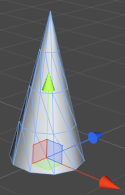
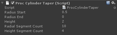
Another possible deformation is a taper. This requires two radii, and our code interpolates from one to the other.
float heightInc = m_Height / m_HeightSegmentCount;

for (int i = 0; i <= m_HeightSegmentCount; i++)
{
	Vector3 centrePos = Vector3.up * heightInc * i;
	float radius = Mathf.Lerp(m_RadiusStart, m_RadiusEnd, (float)i / m_HeightSegmentCount);

	float v = (float)i / heightSegmentCount;

	BuildRing(meshBuilder, m_RadialSegmentCount, centrePos, radius, v,
		i > 0, Quaternion.identity);
}
We’re now calculating the radius inside the height loop, and interpolating from the start radius to the end radius. Setting either radius to zero will give us a cone.
But we’re not quite done yet. Our normals are still facing straight outward, instead of being tilted by the slope of the cylinder. We can’t fix this by rotating each ring, as that would rotate every vertex in the ring uniformly. What we need is an offset, so each normal can be adjusted relative to its base, horizontal value.
float heightInc = m_Height / m_HeightSegmentCount;

Vector2 slope = new Vector2(m_RadiusEnd - m_RadiusStart, m_Height);
slope.Normalize();

for (int i = 0; i <= m_HeightSegmentCount; i++)
{
	Vector3 centrePos = Vector3.up * heightInc * i;
	float radius = Mathf.Lerp(m_RadiusStart, m_RadiusEnd, (float)i / m_HeightSegmentCount);

	float v = (float)i / heightSegmentCount;

	BuildRing(meshBuilder, m_RadialSegmentCount, centrePos, radius, v,
		i > 0, Quaternion.identity, slope);
}
We are using the difference between the start and end radii and the height of our cylinder to calculate the slope (or rise and run, or tangent) of the cylinder.
Now to tell BuildRing() what to do with this value:
void BuildRing(MeshBuilder meshBuilder, int segmentCount, Vector3 centre, float radius,
	float v, bool buildTriangles, Quaternion rotation, Vector2 slope)
{
	float angleInc = (Mathf.PI * 2.0f) / segmentCount;

	for (int i = 0; i <= segmentCount; i++)
	{
		float angle = angleInc * i;

		Vector3 unitPosition = Vector3.zero;
		unitPosition.x = Mathf.Cos(angle);
		unitPosition.z = Mathf.Sin(angle);

		float normalVertical = -slope.x;
		float normalHorizontal = slope.y;

		Vector3 normal = unitPosition * normalHorizontal;
		normal.y = normalVertical;

		normal = rotation * normal;

		unitPosition = rotation * unitPosition;

		meshBuilder.Vertices.Add(centre + unitPosition * radius);
		meshBuilder.Normals.Add(normal);
		meshBuilder.UVs.Add(new Vector2((float)i / segmentCount, v));

		if (i > 0 && buildTriangles)
		{
			int baseIndex = meshBuilder.Vertices.Count - 1;

			int vertsPerRow = segmentCount + 1;

			int index0 = baseIndex;
			int index1 = baseIndex - 1;
			int index2 = baseIndex - vertsPerRow;
			int index3 = baseIndex - vertsPerRow - 1;

			meshBuilder.AddTriangle(index0, index2, index1);
			meshBuilder.AddTriangle(index2, index3, index1);
		}
	}
}
First, we calculate vertical and horizontal lengths for our normal value. This is done using the slope vector, rotated 90 degrees. Our unit position is horizontal, so we multiply this by the horizontal scale, and plug the vertical scale directly into the normal’s Y value.
That done, we apply the rotation value, so that the normal is rotated along with the position.
And that’s our taper.
Combining bend and taper
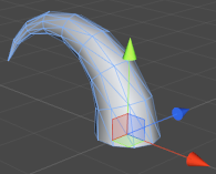
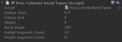
To get some more interesting results, we can combine two of the deformations we’ve learned so far, bend and taper:
float bendAngleRadians = m_BendAngle * Mathf.Deg2Rad;
float bendRadius = m_Height / bendAngleRadians;

float angleInc = bendAngleRadians / m_HeightSegmentCount;

Vector3 startOffset = new Vector3(bendRadius, 0.0f, 0.0f);

Vector2 slope = new Vector2(m_RadiusEnd - m_RadiusStart, m_Height);
slope.Normalize();

for (int i = 0; i <= m_HeightSegmentCount; i++)
{
	Vector3 centrePos = Vector3.zero;
	centrePos.x = Mathf.Cos(angleInc * i);
	centrePos.y = Mathf.Sin(angleInc * i);

	float zAngleDegrees = angleInc * i * Mathf.Rad2Deg;
	Quaternion rotation = Quaternion.Euler(0.0f, 0.0f, zAngleDegrees);

	centrePos *= bendRadius;
	centrePos -= startOffset;

	float radius = Mathf.Lerp(m_RadiusStart, m_RadiusEnd, (float)i / m_HeightSegmentCount);

 	float v = (float)i / m_HeightSegmentCount;

	BuildRing(meshBuilder, m_RadialSegmentCount, centrePos, radius, v, i > 0, rotation, slope);
}
This really is a straight mash-up of the two deformations. We’re using our bend code, plus an interpolated radius and a slope offset, taken straight from our taper code.
That’s it for this tutorial. See you in the next, and final, part, where we make some much more interesting shapes: mushrooms and flowers.
On to part 2B: Making cylinders interesting

3 Responses to Modelling by numbers: Part Two A